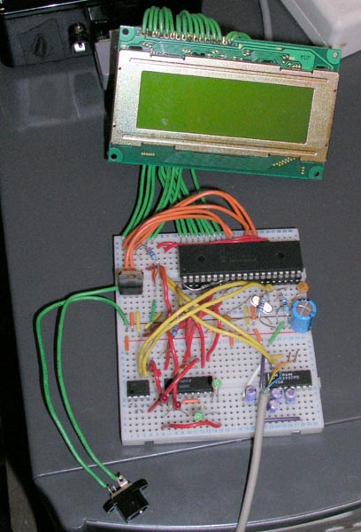
The most obvious addition is the LCD screen. I added that as an aid to debugging mostly, but it is much easier to see what is going on with a nice display. I have decided to include an LCD in the final design as an option, there will be a spare i2c header on the PICPEC circuit board for expansion purposes and things like the LCD panel can be added if they are wanted via a seperate PIC/LCD control board. Another extra will be from optical encoders so that digital setting circles can be easily added, and also a board for a motorised focusser. I will budget for the LCD system in the main costs as I think it is very useful, but not the setting circles (although I can probably still do this under budget if I did). I have a set of 16x2 LCD screens winging there way to me from Australia right now, Ł12 for 6 screens from ebay isn't to bad. This will not be backlit though, unless I find somewhere to buy flat red LED panels from. I don't want to use yellow or green unless it really is to hard to use without a backlight (I have tons of light pollution so it makes little difference to me). Maybe a yellow light with red cellophane over the screen will work alright?
The other addition is the small chip on the bottom left of the board. This is a 4kb EEPROM chip, accesible via the I2C serial bus protocol.
The current state of the code is to display the current status on the LCD panel, which directions the controller is moving the scope in, and incoming commands from the PC. Also I have just finished the EEPROM access code and can now save and retreive data from there. Next job is to rig up a trigger and button so that I can simulate a PEC training session and playback. Once that is done, the thing is pretty much complete. I will just need to work out a decent physical user interface (such as having a single button for control or two/three, etc) and laying out a proper PCB to put the circuit on. Also I need to build a seperate circuit for the LCD panel, I will use another PIC for that though, so when PICPEC starts up it can query for other devices on the I2C bus and use them if they are there. I am going to add a couple of 4-pin connectors to the outside of the box for expansion ports for the two external components (encoders and focusser).
Current PIC situation -
Update - 4th October 2004
After some testing I found a problem that was causing PICPEC to be very unstable. Most of the main players in the autoguiding field (K3CCDTools, GuideDog, etc) were causing PICPEC to lock up, while a simpler guider I found (Star Track) worked fine. I had been using Star Track anyway so I hadn't noticed it very much. The problem was that PICPEC was missing the occasional character over the serial link, and sometimes missing loads of a long string of commands. This is because writing to the LCD and EEPROM need time delays to communicate properly and the tiny serial buffer on the PIC chips (just 3 bytes!) was overflowing. So I decided to move the serial receive routine into an interrupt so it always got the character. But this still gave the same problem. Most of the LCD output is done while checking the incoming command and parsing it, so by the time the first letter or two had been checked, the last few had been missed. I have now (finally) solved this by allocating a big block (78 bytes) of memory to use as a circular software receive buffer. Now the receive interrupt routine just adds the incoming byte to the end of the buffer and the main code can process it at it's leisure. I had to solve some problems due to bank switching all over the place that stopped me for a day or so, and had to learn how to use interrupts and indirect addressing. The most I have seen any of the guiders send is about 5-6 commands in a row (30-35 bytes max) and the buffer is processed pretty quickly so it should be ok to use like that. If it does cause a problem I can increase the buffer to 94 bytes fairly easily, or 126 bytes with some more complexity, but I will be starting to max out the available memory on the PIC16F628a that I am targetting.
Current software that I have tested is -
I have also added an extra option. It occured to me that I needed a way to clear the EEPROM so I have added a 'Factory Reset' option. If you hold down the button (oh yeah, I added a button and the PEC synch trigger as well, but they aren't really used yet) when you switch the power on, it blanks the first 1k of the EEPROM, which is enough for a 17 minute worm cycle (normal mounts seem to have about 8-10 minute cycles). There is a progress display and a message at the end, but it only takes about 5 seconds to clear anyway.
Finally I am in the home straight. All I have to do is add support for the button and the synch trigger and I should be able to test it at last. I am probably going to add an extra button as well to allow the PEC to be paused as I still have 3 (I think) free pins on the target PIC.
I am still waiting for my 16x2 LCD panels to turn up from ebay, hmmm. No rush yet though, I am planning to do some serious imaging before I go from breadboard prototype to a PCB in a project box production model where I will need a smaller LCD :)
Update - 6th October 2004
I blew my PIC chip, hmmm. One of the ground leads going to the PIC had come loose, which I noticed when it touched the 12v power supply, oops!
So I had a couple of choices, order another one full price from Maplin and wait a few days for delivery, port the code to the 20-pin 16F628A PIC that the final PICPEC will use, or port the code to a 40-pin PIC 18F452 that I have a couple of. I decided that I would use the bigger 18F452 PIC because it is pin compatible with the one I blew and I wouldn't have to change the circuit. Porting to the 20-pin PIC would have been extra work as I would have to build the I2C LCD interface and a 40-pin to 20-pin adapter to program it with and it will be quicker not to do those for now. This is the first time I have tried the 18F series and they seem very good, porting the code only took about an hour and a half, but most of the day was spent trying to get the LCD working again. It has power (the character cells darken a bit when it powers up) but I can't get anything to display on it now. I spent ages trying various things with the PIC setup in case that was different, but using a multimeter all the signals are being sent so I have to assume it is dead as well. So I debugged via the serial link and it all works as it was this morning again, just without a display :( I will build a test circuit for the LCD sometime soon in case it is still a PIC issue but I don't hold out much hope now after trying a load of stuff. As both the PIC and LCD were not the ones going to be used in the final model, I am not adding them to the costs, that is supposed to be the cost of a new unit, not development costs as well.
Anyway, The changes I made since the last update were to implement a state system so that different code paths get taken in the different PEC modes (waiting for initial trigger, learning, active, paused, etc). This just displays on the screen which mode it is in at the moment and makes the status LED (also new) flash at a different speed depending on the mode so that people without an LCD (like me for now) can tell which mode it is in. The flashing speeds I choose arbitrarily are -
Update - 14th October 2004
Two bits of good news. Firstly the LCD wasn't dead, it was a quirk of the new PIC chip that meant one of the pins I was using to send data to the LCD was turned off for i/o by default. It happened to be the same pin that is used in the command to turn the LCD on so it looked like it didn't work until I found out about that bit.
Secondly, and most importantly, PICPEC is ready to test!
I have been testing and adding new code and believe that it has finally got all the abilities it needs to be able to run successfully. I have done equivalent practise sessions indoors and it certainly looks like nothing is missing. I did what I said last time and a button press pauses it, while being held for 3 seconds makes it go to training mode where it waits for the trigger before recording the PEC data to EEPROM. That is working fine, as is the EEPROM PEC playback code in active mode. When the trigger gets knocked the second time in training mode it automatically starts the main PEC active mode and starts playing back. Here is the latest circuit -
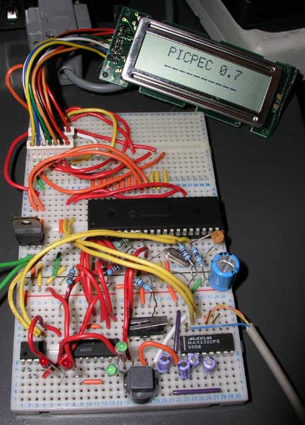
Note the new LCD displaying the splash screen as well :)
I updated the display code to fit the new LCD when they finally turned up a day or two ago. Here is what is seen while it is actually running -
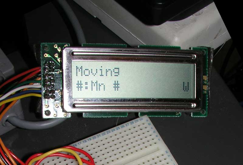
It only displays autoguide data at the moment in the main part of the screen. The top line is what command it is running (Moving, Stopped, Get RA, Get Dec, Get Sidereal, Unknown), the bottom line shows the LX200 command used to initiate that action. On the bottom right is the mode that PICPEC is currently in, W - Waiting, A - Active, TW - Training (waiting for first trigger), T - Training. I will remove the LX200 command and use the space for something more useful later on, it is mostly for debugging at the moment.
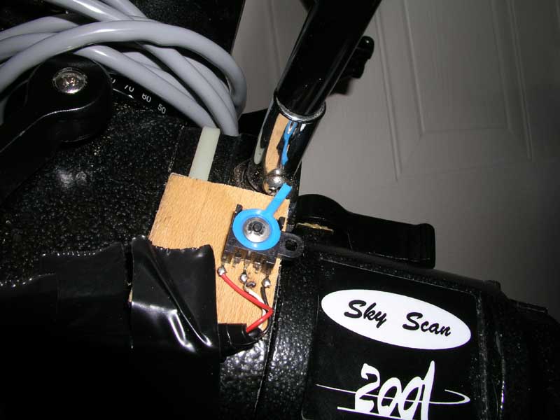
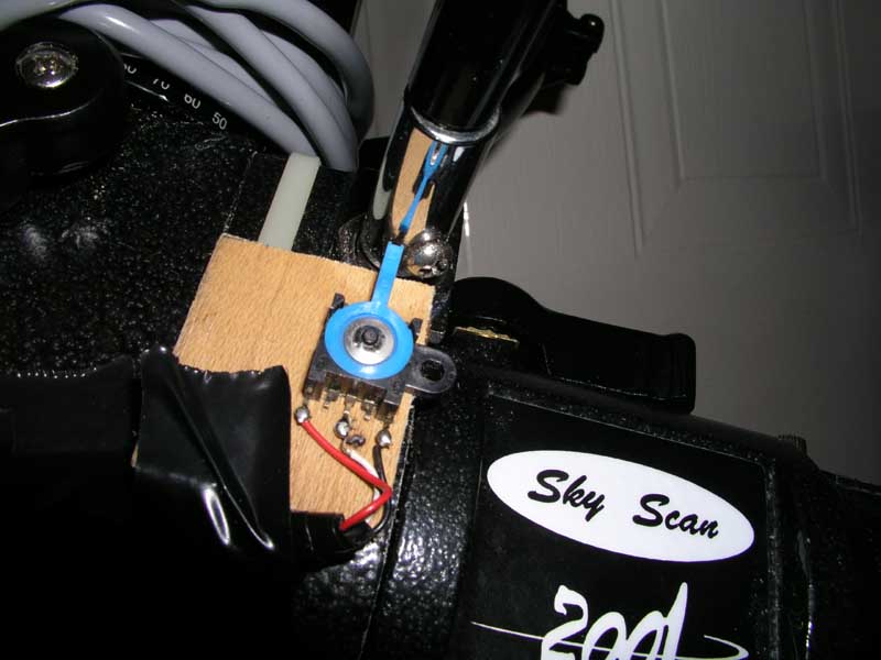
I have also got 2 pictures of the sync trigger I am using. It is a two-way lever that is sprung to always return to the centre that I got out of an old fax machine while salvaging parts a while back. Whe it is moved to one side or the other, it connects internally and the processor can decide what to do, no signal is sent while it is the centre. I have mounted it on the other side of the RA worm shaft from the motor, where I have mounted the slow motion control knob. I am using the screw that holds the knob on to activate the trigger once per cycle. The first picture shows what happens when the screw hits the trigger. It is moved to one side. The second picture shows a few seconds later when the screw has moved too far and the trigger springs back to the center. That is the point where sync is made, when the trigger is released after being held down for more than half a second (to avoid electrical noise or a hand in the dark accidently triggering it) -
I have decided to change the PIC chip that the final version will use. I am still going for an 18-pin version (the old one was actually 18 not 20-pin as I have been saying, oops), but based around the newer PIC18 core that I am using now. Not because they are better but because they have 2 very useful features that wil help. They have an internal EEPROM of 256 bytes. This isn't enough to store the PEC data at the moment, as it is 1 byte per second, therefore around 600 bytes, but I am going to investigate whether storing one correction every 4 seconds will work as well if the correction is spread out over the 4 seconds (each correction divided by 4 and applied once per second). This would then use just 150 bytes and allow me to get rid of the seperate EEPROM chip, which will keep the part cost down. The other advantage is that the PIC18s can write to program flash memory. This means that once the chip is programmed once, firmware updates can be sent over the serial link from the computer. That means that not only will it make my life easier developing it, but hopefully anyone else that decided to build one as bugs can be fixed without them having to have a PIC programmer. The chip I have decided on is the PIC18F1320 and I have bought a few for Ł2.35 each, so it isn't a huge increase in cost, offset exactly if the EEPROM chip can go. I could use the old chip for the LCD controller to save 75p, but I think it is easier to keep both chips the same for ease of purchase. All the major electrical parts are accounted for now though, the only other big costs are going to be a project box and connectors, other bits like chip sockets, resistors, leds, etc are cheap.
At some point I need to add the support to adjust the PEC cycle if the controller buttons are used or if guiding commands are sent from the PC, but for now that is ignored. Small movements (up to 5-10 seconds total) won't matter too much unless there is major high frequency periodic error, and it will re-synchronise every PEC cycle anyway if longer movements are made. I also need to add a pause during active mode, currently it is only in waiting mode, to stop PEC from starting while I test autoguiding etc.
Hopefully the next update will be a successful test, maybe with a nice astrophoto as proof :)
Cost does not include negligible items that any hobbyist electronics person would likely already have such as wire, solder, PCBs/breadboard, cable, etc. It will include ICs and discrete components however.