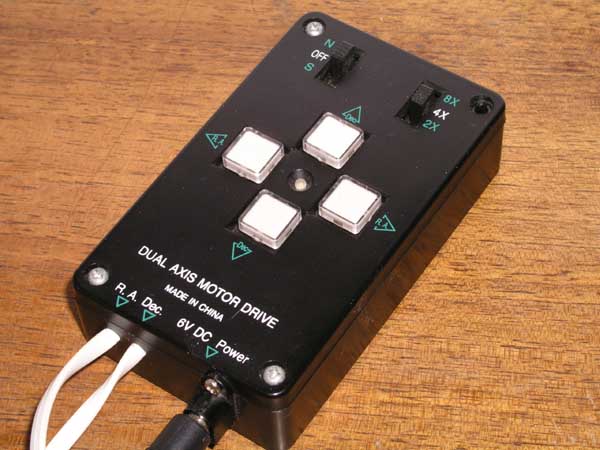
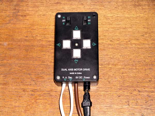
This is the EQ3-2 handset -
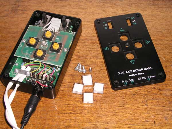
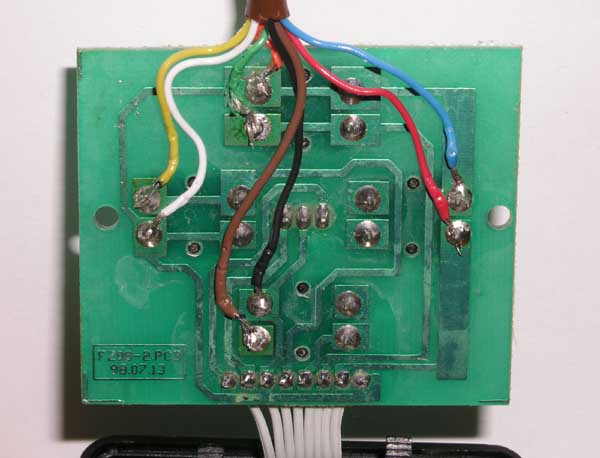
And inside -
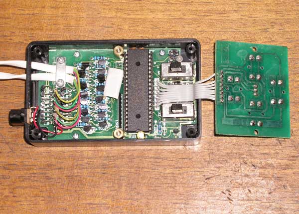


The large chip is a GMS97L51, an 8051-based microcontroller that has 4KB EPROM and 128 bytes of RAM. Although it doesn't matter for this mod, it may be worth investigating at a later date. If it is the reprogrammable version and has not been copy protected it may be possible to reverse engineer the ROM and add this entire PEC mod to a larger capacity equivelant chip.
We are interested in the button circuit board. It is pretty simple to understand, and the first thing I did was to see which way around the switches were wired.
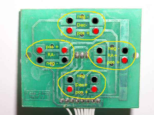
Note that one of the switches is reversed, lucky I checked all of them or I would be wondering why it didn't work at the end. These switches have 4 pins each, but I confirmed that the top two of each button were linked electrically, and so were the bottom two so it doesn't matter whether we use the left or the right of each pair. I soldered a couple of temporary wires onto the Dec- button pads, plugged in the power and the Dec motor and turned it on. Touching the ends of the two soldered-on wires made the motor turn as expected. It's a very simple test but I wanted to confirm that the switches did just make or break a contact rather than do something I hadn't unexpected, can't be too careful.
Next I made a simple test circuit and program using a 40-pin 16f77 PIC that I had in my supplies. I am not adding this to the cost as it is for testing only, the proper circuit will use a cheaper 16-pin (probably) PIC that I will put in the costs. The circuit alternately flashed a red and a green led at roughly 1 second intervals and nothing else. Once that was up and running I removed one of the leds and put an opto-isolator chip in it's place. I haven't used one before so I did a quick check with a mini-circuit on the other side of the isolator that just had an led that was turned on and off by the isolator. I replaced the mini-circuit with the two wires coming from the handset, making sure that I have the positive and negative the right way around. It worked as expected and holding the motor in my hand, I could feel the steps ticking away, on for a second then off for a second.
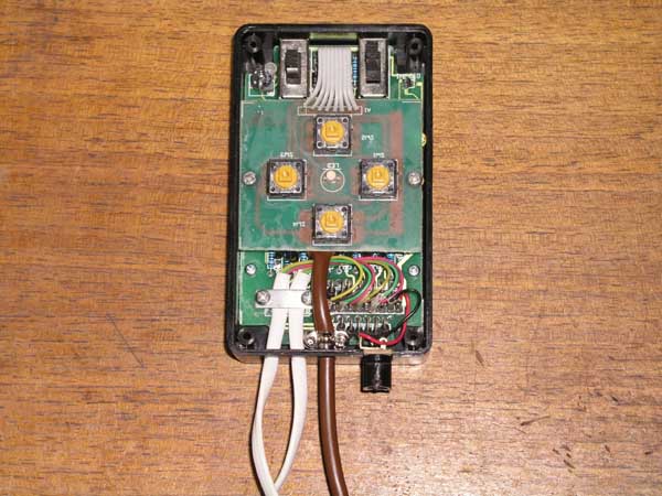
I removed the (fairly stiff) test wires and soldered each wire of an 8-wire cable to a terminal, noting which colour went to each one. Even though on the circuit board all the buttons shared a common ground I soldered a seperate wire to each. I did this so that if anyone else does decide to do the same mod, then it creates a common interface whatever the internals of the handset. And I happened to have 8-wire cable, so why not :)
Not the neatest job in the world, but not bad for me and the wires seem firmly attached and the joints sound. I also checked with a multimeter that there were no solder bridges. Next I drilled a hole in the base of the handset next to the RA and Dec motor wires and threaded my cable through it. I used the metal wire clamp that comes in a serial connector to grip the wire inside the handset and make sure that any tugs on the wire don't rip the new solder joints apart making sure that it couldn't touch any exposed wires. I then screwed the button circuit board back into the handset. It is a tight fit but it just about fit in around some diodes in the base of the unit
Finally I put the handset lid back on and did a final test my powering it up and touching the pairs of wires together at the end of the new cable to make sure that they did trigger the motor in the right directions. That's it for the handset for now, everything we need to modify should be done. The logic to check if a key is being pressed will work by checking if the voltages on each pair of wires is different using a quad xor logic chip (with the voltages reduced to TTL levels of course). If they are different (outputs logic 0, low signal) then the button is unpressed, if it is the same (outputs logic 1, high signal) then the button is being pressed. An interrupt on the microcontroller will monitor this and update itself accordingly either for the learning phase or to update the position in the PEC table if the handset is used to alter the position. I may return to open up the handset again to monitor the speed switch, but that will depend on if it causing a problem with the position in the pec table getting majorly out of sync with the worm scope. At the worst it would correct itself after 10 minutes and with the slow slewing speed it would be easier to move the scope manually than to use the handset for a large change.
(update - 6th June 2004)
This is my first test circuit for auto-guiding
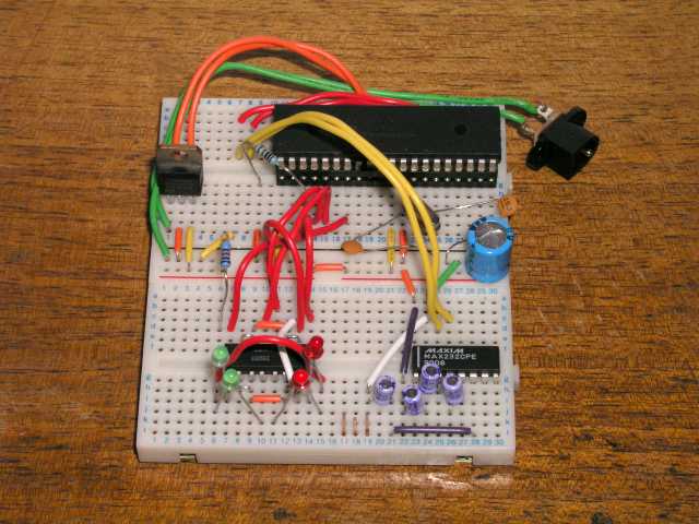
I am still using the 40-pin PIC for testing as I haven't yet built an adaptor so that a 20-pin one will fit my programmer, but I have bought a couple of 20-pin PICs now to use which I will use before I add the PEC component. The other two chips are a 4-channel opto-isolator (left side) so that the 2 different circuits (handset and this one) don't interfere with or damage each other, and a MAX232 chip (right-side) to convert PIC voltage levels into PC RS232 voltage levels. The serial cable from my laptop connects to the 3 gold pins in the center at bottom. The PIC is programmed to accept #:Mx# and #:Qx# commands from the LX200 scope command set, this means I can use existing software to guide the scope with and I have been using K3CCDTools version 2 to test with. There are 4 LEDs on the bottom left that serve for testing for now to signal which button on the handset this device will be activating. I haven't yet decided whether to put similar LEDs on the finished device or not. I cut the cable off an old serial mouse to use to connect to the device, so that was free. When the handset is connected instead of the LEDs the motors turn as expected and seem to be perfectly normal. I haven't yet had a free clear night to test it with properly though so I will wait before testing any more.
Update - 17/09/2004
I have now tested the circuit with the telescope and it works for more than 10 minutes at a time. The only problem being my motors are not very good and sometimes they run away a bit. For example the coupler that connects the RA motor to the worm shaft has a bit of backlash. This means that if you move west using the handset it sometimes takes a few seconds for the stars to stop moving. That is something I need to fix independantly from PICPEC though. For small pulses used in guiding it doesn't really effect anything, I just need to fine tune the guiding parameters in the software I am using so that it doesn't happen during PEC. I have also added a couple of other LX200 commands, mainly a few from the #:G# series which gets info like RA, Dec, Sidereal time, etc. This is because the ASCOM driver needs those things to connect to PICPEC and I just return blank data that is in the right format.
Cost does not include negligible items that any hobbyist electronics person would likely already have such as wire, solder, PCBs/breadboard, cable, etc. It will include ICs and discrete components however.